
I am using, again, Carrara. At moment I'm on the latest version, number 8 (which they have finally fixed the majority of bugs on... after a mere 9 months!), but my tips for today are good for any version of the program (and even its ancestor software Raydream).
Where I am a real rebel is I will be showing you how to make a Dinosaur today with a Spline editor. Most 3D people make organic creatures with Vertex or Metaball methods. So if you're looking for insight into those realms I am not the guy for you.
So what is a spline object?
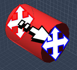
A spline is an "object" created by drawing several cross sections along a linear path, and filling in the spaces between the cross sections with "mass". While this might sound complicated it is actually rather simple.
Using this simple cylinder above as an illustration, the cylinder is formed by a single circle cross section which the computer stretches along the line to create the remaining mass. If you were to insert additional cross sections and change them from simple circles you can make your arm (as an arm is basically a slightly distorted cylinder).
If this still doesn't make sense, hopefully it'll make more sense as I jump into how I make my Dinosaurs.
 So Carrara people, you're going to have to create spline objects to follow my technique. The necessary icon is show above when starting in the overall modelling window of a new project.
TIP: Try to drag the spline tool towards the middle of the modelling grid so you're object isn't huge or way off the modelling plane.
 Once you create a spline object you should pop into here, the spline editor. Welcome to my workshop of wonders...
If you want to model in here you'll have to learn and master the use of the extrusion path (those purple lines you hopefully can see on the grids above... sorry the picture was shrunk in the upload).
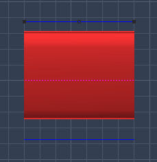
 Taking a closer look at one of the extrusion paths (there are two out of the three possible planes. Here I'm looking at the Y path... you will also in the long run want to get to know the Z plane path as well), the key thing are the extrusion points. Those are the black dots you can see on the purple line.
Whenever you create a new Spline object you will start with a basic extrusion path. This has a cross section point (red arrow) and a extrusion point (blue arrow). You are not restricted too, nor will you typically use, just one of each. You can have as many of either as you want. Though the more points you add the more difficult it will be to manage certain attributes on your object (but too few will make your life difficult with the other attributes... there is always a cost to these things).
What is the difference between a cross section point and an extrusion point?
The main difference is that a cross section point will more define your objects make up and look, while an extrusion point is a means of subtly influencing and tweaking the object. Both are necessary, but cross section points in the end are the most important.
 So let's start with cross section points, as 1. their the most important and 2. you can't start really creating an object without cross sections.
Again a new Spline object starts with a single cross section point at the back of the extrusion path.
Tip: Sadly there is no display difference between a cross section point and an extrusion point. They both are displayed as black dots. You'll just have to try and remember which are which. If you loss track (don't worry we all do) swap to the director's camera point of view which will let you easily and quickly see which are which.
Selecting one of the shape primitive options from the top icon bar, draw an initial shape on the cross section.
If you stick with the initial format of a new spline, you're object will be determined from its back end. While in some cases this might be handy for some types of models, in my experience it is not so good for organic parts.
We're going to want to customize your initial setup.
 Grabbing the add point tool, shown above, you can click on either extrusion path (side or bottom) to add a point. Remember to press the ALT key if you want a cross section point. Just left clicking with the add point will give you a standard extrusion point, NOT a cross section!
 That should give you an object like this. Note how I now have 2 cross sections (both circles, but this will not be the case for long) out of 4 points. Those other two points, while not defining my objects overall shape, will be important to close the object with a solid end point.
 Next I personally like to get rid of the cross section at the end of the path. The reason being that cross section have a greater effect on the objects shape, and in the ends I like to have a more easy and subtle means of controlling my object.
 This now leaves us with a perfect starting point for ANY body part of a Dinosaur you might want.
 Again so you understand what is happening the cross section (red) is defining the extrusion points (blue), and at moment as I haven't modified any attributes of the extrusion path or added any more cross sections I'm getting a perfect cylinder.
 First we're going to want to change our cross sections. I personal like to start with a single customized cross section (as opposed to a generic circle of square), and work off this on all new cross sections.
To customize a cross section shape I personally start off with a primitive shape (typically a circle). I will than ungroup the shape to allow me access to its controlling points. To do this select the shape by clicking on it, than either by going into EDIT and choosing Ungroup or simply hitting Control U.

 So to easier see how we're changing a cross section we'll want to switch viewpoints. Selecting our view point option pick either Front or Current Selection to get a clear view of a cross section.
 Okay so here is your cross section up close and personal. Again this is the best when to manipulate a cross section. At least at the start of modelling.
 To more easily customize our circle we're going to want to add points. For this select the add point tool again, and add some points to your circle where ever you are going to want to pull, distort, or reshape the cross section's shape.
  Pulling the points around the cross section plane, and modifying the curve with the vector points you can start to make Dinosaurian looking cross sections.
 In any envelope your points will suddenly appear above and below your extrusion path alone both extrusion axis. The points will all be connected by blue lines. This is simply a visual means of seeing how your objects points are connecting to each other.
 You can grab any of these points and move them along the extrusion plane. Depending on the type of point and the envelope you have selected different things will happen.
Moving a Cross Sections point here will cause every non Cross Section point connected to it up until the next Cross Section to move with it in proportion to how much you move that one Cross Section. If you are in a symmetrical envelope the other point(s) of that particular section will move accordingly.
Again testing out and playing with this part of splines will clear up any questions you have.
 Lastly you can curve and smooth out the connections between points. To do this you'll need to select the vector tool as shown above.
 With this you can give any point along the extrusion path vector handles that will allow you to curve the connection lines and thus curve your object.
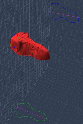
Applying multiple cross sections along the path, modifying their shapes individually, and finally editing their connections along the extrusion path is exactly how I create and modify my Dinosaur parts.
This just requires multiple rounds of all the steps I just outlined for you in this lesson. If you found this useful or interesting let me know in the comment section below, and I will do more if people want more.
Till then happy 3Ding, and good luck with your own three dimensional prehistoric creatures!