As you've no doubt noticed ART Evolved has started to be consumed by excitement over the upcoming Pterosaur Gallery. For really good reason too. Pterosaurs have always been a huge icon of prehistory. So be sure to get started on your entry for the gallery today!
However I'd like to return to the
Synapsids one more time, before it is nothing but flying reptiles around here ;p
Following
Zach and his
examination the creation of his own entry, I wanted to similarly share the process behind my own Synapsid piece. Where Zach approaches his with some regret (I personally think he is being too hard on himself, but I know the feeling. We are often our own worst critics!) I come at my own much more pleased.

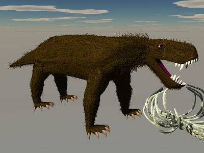
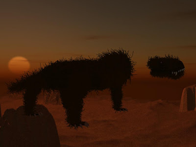
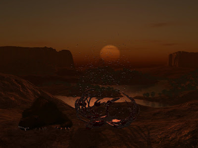
The piece in question is this, Karoo Sunset. I aimed to have a picture that looked like a snap shot of the life in the day of. Unlike usual though, I actually ended up with something resembling what I'd intended.
`
After reading Peter Ward's book
Gorgon (
my brief review here) I felt inspired by the late Permian and the creatures from then we find in South Africa (the Karoo region in particular). Among the few well known and famous animals of this time and place were the Gorgonopsids, so naturally I wanted to recreate them.
`
I had in my mind a scene with a pack of these animals settling at sunset (though there isn't any real evidence I've read about indicating they were social). In that initial imagined state I imagined the piece as a lot more close up and tight then it ended up.
`
However despite it "opening up" all the key elements ended up in the final piece. An animal nawing away at the day's kill, youngsters tumbling around in play, several starting to doze off, and a larger adult showing off its freightening teeth in a big yawn.
`
Though the scene worked out well, I certainly didn't have a plan that lead me to this end product. In fact to be honest I mostly fluked my way there...
Of course the first step was to build a Gorgonopsid. As I work almost exclusively in 3D CG, I'm quite literal when I say build.
`
I was thinking about ART Evolved while building my Gorgon's head (the first thing I tend to build on any animal), and so documented nearly every major modelling step I took to create the skull and jaw. You'll find it all compiled into this little slideshow.
`
This was in total about 45min to an hour of work. It is kind of depressing that it all compresses into 30 seconds so easily...
`
Sadly Gorgonopsids being Synapsids have fairly boring skulls from a construction point of view. They don't have the fun holes and openings of reptilian skulls like Dinosaurs. So if people find this animation neat I'll record the next Dinosaur I build so you can see how a more complicated build comes together.
This one had only one minor 3Ding drama, that being the eye placement. You can see me correct this around 21 seconds.
Anyways with the beast built now I needed to texture it...
This ended up being the most difficult phase in the end.
My first problem was I couldn't decide on what I wanted it to look like. Was it going to be scaly with just some tuffs of fur, or was it going to have a big woolly coat.
`
In the end due to my embarassing attempts at scales with tuff of fur, I opted for just a hair covering.
`
With just a hair covering, creating the baseline model texture was stupid easy. Just this simple brown with black random lines, to simulate a base coat of fur, done on a much larger scale.
However this basline was going to need some 3D fur to make it looking convincing. Enter the HUGE problem. Fur...
Now as readers of my other blogs know, I've been doing a lot of feathered theropods lately, and these have really brought some of my 3D Dinos up to a new level. However you'll also find that despite my love of them in the the final product, feathers (and in this case fur, which is just a slightly different application of the same process) are
the bane of my existence!
`
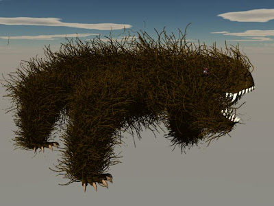
This was among my first attempts at applying hair to my Gorgon... A very cool effect (one I'll be stealing for any woolly animal galleries we do here in the future ;p) but certainly not a realistic looking Gorgon!
Why the crazy non-fur looking fur?
`
I'm using a feature of Carrara called Surface Replication. In it I select any smaller objects (in this case the different individually modelled hairs you see floating above the Gorgon) that I want copied along the surface of a larger object (in this case the various parts of the Gorgon). This feature in theory is incredibly handy, as you can make up to 10 000 copies of the smaller shapes with this utility. Individually placing and modelling that many hairs would take me months (and I just won't do it!).
`
However sadly it isn't as easy as you'd hope. There are a number of factors making it difficult. The size of the hair in comparison to the body ended up being a critical issue, and one I'd hit in a really hard way putting my scene together... I'll get back to that soon.
The thing that bugs me the most about this application is that whoever programmed this feature didn't think about the orientation controls. In theory the fur on my beast should align to the master object (again floating about the Gorgon), however somewhere in the math of this process all the X, Y, and Z attributes swap. Meaning that how I align my fur in the "real" world isn't how they align on the creature.
`
Which is why he appears so shaggy in these early attempts. Fur (or feathers) that stick out make your critter look unkept and unhealthy. So it'd be nice to have intuitive control on these things to slick them back...
`
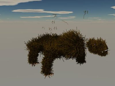
So after playing with the size to body ratio, and the orientation of my fur...
`
I finally got this final version (well okay close to final. I didn't save a shot like this of the final final model).
I went for mostly subtle sized hair, but a larger thicker "mane" around the neck. In this pic it doesn't look so good (as it is also one version before my final one), but in the final piece the manes on the adults worked.
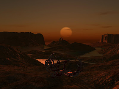
Next I came to where I was going to stick my critters for the scene. The Karoo 250 million years ago was a semi arid desert. Once it'd been a lovely productive forest, but with the number of converging geologic factors caused by the formation of Pangea, the world was slowly being turned into a giant desert...
`
This meant that I didn't just need a desert shot, but due to my desire for a sunset, a desert in sunset. As I didn't have any photos that matched this description, it meant I was going to have to construct my own location in 3D.
`
Though it was a lot more work then my usual compositing (which is work in and of itself). This would take me a week. However the control this gave me over lighting every element contributed to the awesomeness of the end product.
Building the desert itself ended up being rather straight forward. I went for a mesa valley, containing an increasingly rare lake.
`
Where the terrian was trickiest (other then scaling the landscape to match my Gorgons... but that's in a moment) was lighting it. If you compare this early test render to the last, you'll see my conundrum. Sunsets generate a beautiful range of yellows, oranges, and reds. The question is which of these did I want my scene dominated by.
`
The other complication in this was how many different lights was I going to need?
In 3D scenes the lighting is completely up to the modeller, and there isn't just one type of light that fixes all.
`
I'll probably at some point do a full tutorial on 3D lighting (as I've been learning a lot about it this year), but here is roughly how I lite the scene and solved the color problem.
`
In the end the Karoo ended up with 5 lights. The first one is obvious, and one in the real world you'd expect. There is a great feature in Carrara that not only generates the 3D sun you see in the scene, but allows you to make it a light source that mimics properties of real sunlight (such as the colour, brightness, and even clouds... all of these changing on how you position the sun in the sky... so in this case it helped set a baseline sunset lighting).
`
However if you think about this position of the sun to my subjects, they'd all be backlite and thus nothing more then silouettes. The other issue I had was with shadow casting.
`
To solve the Shadow issue (and a bit of my backlighting issue) I created a general "bulb" light directly above the sun (just above the top frame in the final render) that cast a bright yellow light. Bulb lights work just like a uncovered light bulb, they cast light in every direction.
This first bulb was to lighten up the whole scene, and thus help increase the contrast of the shadows. Due to its better angle I made this my central shadow casting light so all the shadows in this scene aren't strictly scientific from a physics point of view :P.
`
This however made the scene too bright. To darken it back down , and yet better light the objects (if that makes sense) from viewers point of view I created a dark red bulb that I placed directly behind the camera. In essence where the picture was taken from.
`
This lit the scene perfectly, but the Gorgons were still very dark. To fix this I created a lighter red light that was set to only light the creatures (and their fur! Which I missed in first couple passes at the scene). This is a fun benefit of 3D light, unlike real light, you can make it effect only things of your choosing!
`
My last light was for a subtle, but needed effect, and that was the glisten of the uneaten meat on the carcass. This was a nearly white "spot" light, as the pure white mixed with my other scene lights nicely. Spotlights can be thought of as like either a real spot light, or metaphorically like a flashlight. It shot a beam straight ahead of it whereever you point it, but that's it. Only things in that line get lite. In this case just the meat objects on the skeleton.
`
All the individual elements were ready. It was finally time to put them together.
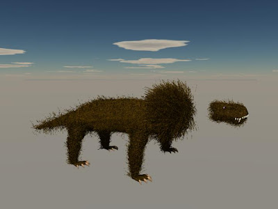
When I hit yet another fur related problem! Which you can see here.
Fur and other surface replicators have another annoying catch. Once you've created them if you change the size of the recipiant object (in this case I had to make the Gorgon smaller, so I shrunk its body parts) the fur doesn't change size to match!
`
I'd modelled the desert on the scale of 200 units long by 200 units wide. My Gorgon was 40 units long. Meaning it was quite large in what should have been a large desertscape. Attempting to shrink my Gorgon caused this fun fur effect...
`
At least my nice lighting obscurred how dumb it is!
`
After rescaling the landscape to an impressive 3000 by 3000 units (anymore then that and my lighting won't work... though this week I have a new means to light even a million by million object!) I had to readjust the lighting a bit. Due to the shift in the sun (to get it back over the now taller horizon) the colour shifted a bit, and I couldn't quite get it back. Oh well.
`
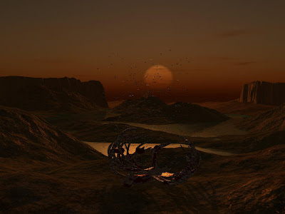
To increase the feel of realism I decided to make a swarm of flies and shrubs scattered aross the scene. These were accomplished like fur (the flies a slight varation, but not worth going into so close to the end).
The last thing I had to do was import Gorgons (sadly one by one) position, pose, and light them. This took a long time just due to the computational requirments of so many 3D objects.
`
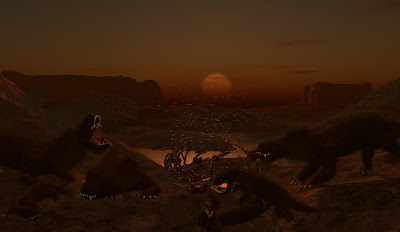
It all came to together as this. Hopefully as you've seen with the errors I documented (and the dozens of others I neglected to document) that though this piece is really awesome, I didn't directly set out knowing I'd get it this way.
`
However this first immersive lesson in lighting has me looking at this factor a lot lately, and I will probably be able to set out for similar effects in the future.
`
What I'm most proud of is that the multi layered lighting has accidentally mimicked the look of a painting. If you can't enlargen this version
here is an enlargened version for a closer up look. This is the closest I've ever come to emulating my childhood hero Charles Knight... Now if only I could actually be as good as him :P


 So
So 

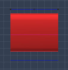
 So let's start with cross section points, as 1. their the most important and 2. you can't start really creating an object without cross sections.


 So to easier see how we're changing a cross section we'll want to switch viewpoints. Selecting our view point option pick either Front or Current Selection to get a clear view of a cross section.
 Okay so here is your cross section up close and personal. Again this is the best when to manipulate a cross section. At least at the start of modelling.
 To more easily customize our circle we're going to want to add points. For this select the add point tool again, and add some points to your circle where ever you are going to want to pull, distort, or reshape the cross section's shape.
  Pulling the points around the cross section plane, and modifying the curve with the vector points you can start to make
 In any
  You can grab any of these points and move them along the extrusion plane. Depending on the type of point and the envelope you have selected different things will happen.
 Lastly you can curve and smooth out the connections between points. To do this you'll need to select the vector tool as shown above.
 With this you can give any point along the extrusion path vector handles that will allow you to curve the connection lines and thus curve your object.
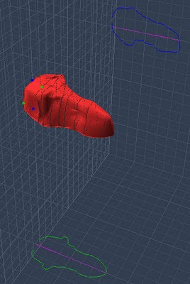


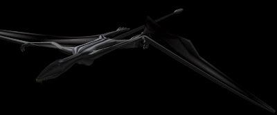
 Here is the finished piece, for reference.
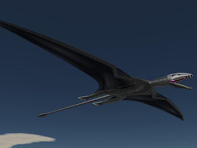 They didn't start this way!

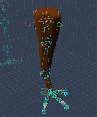 That is of course skeletal rigging. What it does is allow you to define specific points within a 3D object that now act as points of articulation and rotation. In short it creates a real joint.
 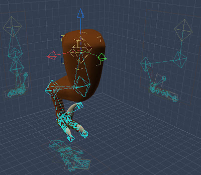 Once applied to a model you simply have to grab one of the diamonds and you can instantly and
 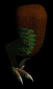 After rigging and posing we get something much more life like!
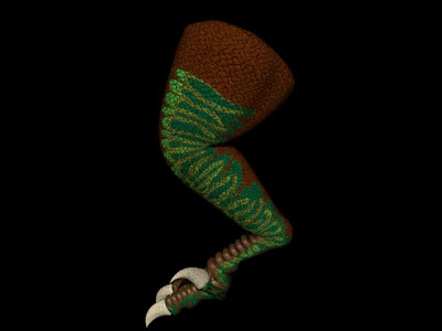 Skeletal rigs take care of all the problems I mentioned before.
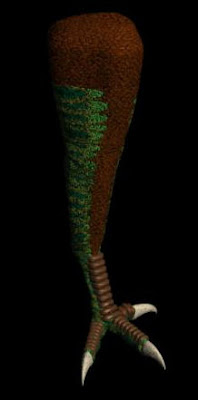
 Not defining any "bones" in the membrane meant the computer could just bend and stretch it
 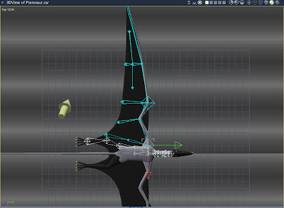 I had my fears that this was going to get complicated (I hate it when I'm right, but we'll get to that in a bit). Just so I would knew, I tried a minimal fix to the problem.
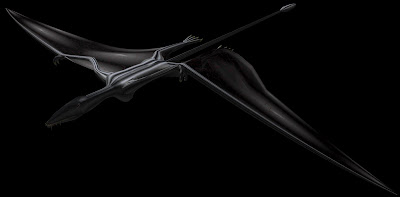 I was half right it turns out. Yes the wing bent perfectly at the

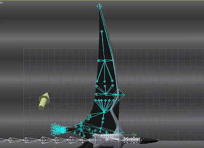 So once again I had to go in and add a dozen branching off membrane "bones" to help define and control the distortion along the legs.
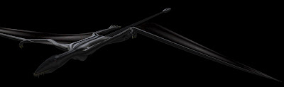 In the end I had a pretty good "simple" rig that allowed me pretty good fluid control on my